Plate Design Settings
- General Overview
- Tips and Tricks
- Related Tools
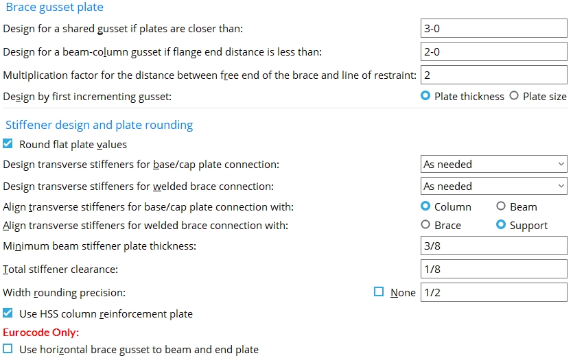
Brace gusset plates
Design for shared gusset if plates are closer than: Any distance ( 0 to 4-0 feet imperial ; 0 to 1219 mm metric). For all types of bracing, this is approximately the distance between the points where the work line of each brace intersects the surface that the gusset attaches to. Since horizontal bracing frames to a beam web, you can approximate this distance by measuring between the work points of the two braces.
If ' 0 ' is entered, the first horizontal brace (the one with a lower member number ) gets a gusset and the other brace gets a plain end.
If the ' distance ' entered here is greater than or equal to the distance that the braces are apart from one another, connection design creates a shared gusset plate. On three point braces, connection design checks the distance between each brace.
A special case: If two braces are farther apart than the distance entered here, but connection design determines that their gusset plates will clash, connection design nevertheless designs a shared gusset to prevent the clash.
Design for a beam-column gusset if flange end distance is less than: The distance from the point where the work line of the vertical brace intersects the beam flange to the face of the column. The face may be the flange or web of the column. This distance is measured parallel with the beam workline.
|
| In the example on the left, the actual flange end distance in the model is less than setup value ( x ), and therefore a beam-column gusset is designed. |
|
You can also get a beam-column gusset for a vertical brace to a column web. The distance entered here, in Plate Design Settings , also applies to the design of such a gusset plate. |
Effect on 3D modeling: This option may be used to prevent connection design from creating gusset plates that are too long. If a vertical brace in Modeling is closer to the column than the distance entered here, connection design creates a beam-column gusset. If the brace is farther from the column than this distance, connection design creates a gusset for the beam only.
Note: The vertical brace workline must go to the column workline in order to get a beam-column gusset. If the vertical brace does not go to the column workline, you either get an error message or you get a gusset on the beam only.
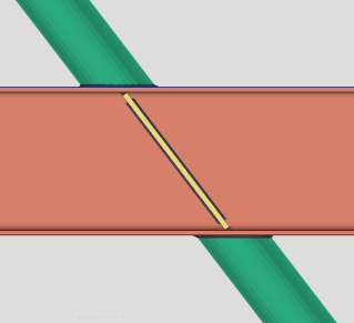
Multiplication factor for the distance between the end of the brace and line of restraint: Any whole number from 0 to 10 . This applies to vertical braces when " Seismic brace " is set to ' Yes ' (or to ' Automatic ' with the setup option set to ' ![]() ') only when '
') only when ' ![]() SCBF ' is selected in Design Settings .
SCBF ' is selected in Design Settings .
factor = ' 1 '
 |
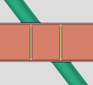
factor = ' 3 '
 |
| The construction lines in these examples are the separated by a distance equal to the thickness of the gusset plate. | |
Effect on connection design : During the design of a seismic SCBF connection, connection design multiplies the ' number ' entered here by the thickness of the gusset plate to set the distance measured parallel with the brace workline from the end of the brace (or paddle plate or built-up tee) to the nearest corner of the gusset plate. Special cases: If the " Pipe/tube end-fitting " is ' Bolted ' or ' Paddle plate ', the distance is measured from the end of the built-up tee or paddle plate to the line of restraint. '
OCBF ' design is not affected by this multiplication factor.
Definition: The "line of restraint" is the plastic hinge location on the brace line. It is a line perpendicular to the brace workline that is drawn through whichever corner of the gusset is nearest to the end of the brace (or paddle plate or built-up tee).
Also see: " Seismic brace " (sets connection type).
Design by first incrementing gusset: Plate thickness or Plate size .
If ' Plate thickness ' is selected, connection design first adjusts the plate's thickness when sizing a gusset plate to stands up to the load. The general result will be gusset plates that are thicker and smaller.
If ' Plate size ' is selected, connection design first adjusts the plate's size when designing it to stand up to the load. Consequently, gusset plates will generally be thinner but larger in size.
Use horizontal brace gusset to beam and end plate: ![]() or
or ![]() . This applies when the " Connection design method " is 'EUROCODE 3' or 'EUROCODE 3 UK'.
. This applies when the " Connection design method " is 'EUROCODE 3' or 'EUROCODE 3 UK'.
|
|
If this box is checked (
), connection design is permitted to weld the horizontal brace gusset plate to the end plate.
If the box is not checked (
), connection design is not permitted to weld the horizontal brace gusset plate to the end plate. In the example above, this results in a connection failure with the message " Gusset interferes with beam connection ."
Stiffener design and plate rounding
Round flat plate values: ![]() or
or ![]() . This option does not affect connection design , but does affect Create Solids .
. This option does not affect connection design , but does affect Create Solids .
If this box is checked (
If the box is not checked (
Design transverse stiffeners for base/cap plate connection: As needed , Always , or Never . This applies when " Use transverse beam stiffener " is set to 'Automatic' in a Column Edit window's " ![]() Connection specifications " for a user base/cap plate or auto base/cap plate to a beam flange. The " Use transverse beam stiffener " connection specification is also available at Home > Project Settings > Job > Connections > Auto Standard Connections and Home > Project Settings > Job > Connections > User Defined Connections . Transverse beam stiffeners can be designed when a column with an auto or user base/cap plate frames to the top or bottom flange of a beam.
Connection specifications " for a user base/cap plate or auto base/cap plate to a beam flange. The " Use transverse beam stiffener " connection specification is also available at Home > Project Settings > Job > Connections > Auto Standard Connections and Home > Project Settings > Job > Connections > User Defined Connections . Transverse beam stiffeners can be designed when a column with an auto or user base/cap plate frames to the top or bottom flange of a beam.
|
|
' As needed ' instructs connection design to create one pair of full-depth transverse beam stiffeners, when the " Load is large enough that the supporting wide flange beam's web capacity is exceeded and stiffeners are required." Two pairs of stiffeners are created when the "Load" is sufficiently large. The two pairs of stiffeners align with the flanges of the column. A single pair of stiffeners is centered with respect to the column work line.
' Always ' instructs connection design to create at least one pair of full-depth transverse beam stiffeners, regardless of the " Load ." Two pairs of stiffeners are created when the " Load " is sufficiently large. The two pairs of stiffeners align with the flanges of the column. A single pair of stiffeners is centered with respect to the column work line.
' Never ' instructs connection design to not create full-depth transverse beam stiffeners, even if they are required by connection design. A red banner will appear in "
Information " that reads "Beam web design checks removed by user". This message will also appear in the column's design calculation.
Related setup options: " Minimum beam stiffener plate thickness", " Total stiffener clearance", " Align transverse stiffeners for base/cap plate connection with ", " Align transverse stiffeners for welded brace connection with ".
Design transverse stiffeners for welded brace connection: As needed , Always , or Never . This applies when " Use transverse support stiffener " is set to 'Automatic' in a Vertical Brace Edit window's " ![]() Connection specifications " for a Welded connection to a wide flange beam, column, or vertical brace flange. The stiffener plates will be located on the supporting wide flange member to stiffen the member's web.
Connection specifications " for a Welded connection to a wide flange beam, column, or vertical brace flange. The stiffener plates will be located on the supporting wide flange member to stiffen the member's web.
' As needed ' instructs connection design to create full-depth transverse stiffeners in this situation only if the vertical brace's " Load " is large enough that the supporting wide flange member's web capacity is exceeded and stiffeners are required.
' Always ' instructs connection design to always create full-depth transverse stiffeners, even if they are not required by connection design.
' Never ' instructs connection design to not create full-depth transverse stiffeners, even if they are required by connection design. A red banner will appear in "
Align transverse stiffeners for base/cap plate connection with: Column or Beam . The choice made here applies to the connection design of transverse beam stiffeners when " Align stiffeners with " is set to ' Automatic ' in a Column Edit window's " ![]() Connection specifications " for a base/cap plate that bolts to the flange of a beam. The " Align stiffeners with " connection specification is also available at Home > Project Settings > Job > Auto Standard Connections and Home > Project Settings > Job > User Defined Connections .
Connection specifications " for a base/cap plate that bolts to the flange of a beam. The " Align stiffeners with " connection specification is also available at Home > Project Settings > Job > Auto Standard Connections and Home > Project Settings > Job > User Defined Connections .
|
|
When " Align stiffeners for base/cap plate connection with " is ' Automatic ' . . .
' Column ' specifies that connection design create transverse beam stiffeners that are parallel with the work line of the column.
' Beam ' instructs connection design to create transverse beam stiffeners that are perpendicular to the workline of the beam.
Connection specifications: " Align stiffeners with " (auto base cap plate) and " Align stiffeners with " (user base/cap plate) use the choice made here (in Cap Plate Settings ) when set to " Automatic ."
Related setup options: " Design transverse stiffeners for base/cap plate connection ", " Minimum beam stiffener plate thickness ", " Total stiffener clearance ", " Width rounding precision ".
Align transverse stiffeners for welded brace connection with: Brace or Support . This applies when " Align stiffeners with " is set to ' Automatic ' in a Vertical Brace Edit window's " ![]() Connection specifications " for a Welded connection to a wide flange beam, column, or vertical brace flange.
Connection specifications " for a Welded connection to a wide flange beam, column, or vertical brace flange.
|
|
' Brace ' aligns the stiffeners with the geometry of the vertical brace.
' Support ' aligns the stiffeners perpendicular to the supporting wide flange member's flanges.
Minimum beam stiffener plate thickness: A distance. Connection design creates beam stiffener plates on a beam (placed over or under a column) that are as thick or thicker than the thickness entered here. The number of stiffeners that are created depends on the " Load " on the column.
Related setup options: " Design transverse stiffeners for base/cap plate connection ", " Total stiffener clearance ", " Align transverse stiffeners for base/cap plate connection with ", " Align transverse stiffeners for welded brace connection with ".
Total stiffener clearance: A distance. The clearance at each end of a stiffener is 1/2 of the "total clearance" that is entered here. ' 0 ' makes the stiffener flush to the surface. Some edges of stiffeners are always flush (no matter what distance is entered here). The table below lists clearances that are governed by the entry made here.
| Stiffener Type | Clearance |
| Full depth beam stiffeners over/under columns. | The top/bottom stiffener edge to the inside of the beam's top/bottom flange. |
| Extended shear plate to column web . | Each edge of stability plate to inside column flanges. |
| Shear plate with stiffener opposite . | Bottom edge of stiffener to inside of the beam's bottom flange. |
| Full depth extended tee for a clip angle , bent plate or end plate connection. | Bottom edges of both built-up tee plates to the inside of the beam's bottom flange. |
|
The clearance at each end of the stiffener is 1/2 of the Total stiffener clearance that is entered here, in Job Setup. |
Also see: Total stiffener clearance
Width rounding precision: The distance that is the precision to which connection design is instructed to round the width of the stiffener.
|
| The stiffener width in the left example is 3 1/8 inch. The example on the right has a 3-inch plate width. |
Connection design creates transverse beam stiffeners whose interior width edge is flush with the web of the beam and whose exterior width edge is as close as the " Width rounding precision " permits to the outer edge of the flange of the beam. In the left example above, a " Width rounding precision " of ' 1/8 ' permits the outer edge of the stiffener to align with the outside of the beam's flanges. In the above, right example, a "Width rounding precision" of ' 1/2 ' creates a narrower stiffener whose outer edge is 1/8 inch inside of the outer edge of the beam's flange.
Transverse beam stiffeners can be designed when a column with an auto or user base/cap plate frames to the top or bottom flange of a beam. For an auto base/cap plate, "
Connection design lock:Plate width (in the "
Use HSS column reinforcement plate: ![]() or
or ![]() . This applies to single-plate shear connections and welded moment connections to vertical brace gusset plates when that connection frames to an HSS rectangular (or tube) column with a thin wall. This may apply to beam connections when " Use HSS column reinforcement plate " is set to ' Automatic '. It may apply to vertical brace connections when "Use HSS column reinforcement plate" is set to 'Automatic'.
. This applies to single-plate shear connections and welded moment connections to vertical brace gusset plates when that connection frames to an HSS rectangular (or tube) column with a thin wall. This may apply to beam connections when " Use HSS column reinforcement plate " is set to ' Automatic '. It may apply to vertical brace connections when "Use HSS column reinforcement plate" is set to 'Automatic'.
|
|
|
If this box is checked (
If the box is not checked (
Connection specifications (beam): Use HSS column reinforcement plate
End connection failure message (beam): Slender col wall - not valid for a shear tab conn
Connection specifications (vertical brace): Use HSS column reinforcement plate
End connection failure message (vertical brace): HSS wall strength fails
Connection design locks (on column): Column Reinf Plate
Connection Guide: Single-plate shear connection
Connection Guide: Welded moment connection
Connection Guide: Vertical brace to column


|
|
OK (or the Enter key) closes this screen and applies the settings.
Cancel (or the Esc key) closes this screen without saving any changes.
Reset undoes all changes made to this screen since you first opened it. The screen remains open.
- Moment Plate Design Settings has various moment settings that were previously located on this screen.
- Red or yellow exclamation point icons
 or
or 
- Connection design (settings on this screen are applied during)

